Enhancing direct torque control of doubly fed induction motor in electric vehicle using artificial neural networks
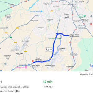
Figure 12 illustrates the route followed by the EV. A real-world scenario is considered in this study, starting from the Higher School of Technology in Fez. This route is based on actual travel data, covering a 12-minute period, and initially involves crossing part of the city, with segments showing speed variations typical of urban traffic, before reaching a highway section where speeds become higher.
This trajectory provides a representative combination of urban and highway conditions, allowing the dynamic characteristics of the journey to be captured and offering insights into the profile to which the control system is subjected. The information extracted from this figure serves as a reference for defining the speed setpoint in the simulation, aiming to faithfully reproduce the variations and demands of the real route.
Fig.12

Real-World Route of the EV Including Urban and Highway Conditions41.
Full size image[1]In this simulation, the speed reference, represented in Fig. 13, was reduced to a duration of 60 s compared to the actual 12-minute duration observed on the route, and this choice is based on several reasons. First, this temporal adaptation is a common simplification in simulations aimed at reducing computation time while maintaining the essential characteristics of the speed profile.
A shorter simulation minimizes resource usage without losing critical information on the dynamic variations in speed. The primary objective of this simulation is to validate the responsiveness and efficiency of the speed control; therefore, reproducing the entire real trajectory is unnecessary: 60 s provide a sufficient timeframe to evaluate the system's performance in response to the typical dynamic changes observed in a real route. Furthermore, this temporal reduction is based on a proportionality assumption, where the 60-second simulated trajectory is an analogous, condensed version of the actual 12-minute trajectory.
In other words, it preserves the general "shape" of the speed profile, including acceleration and deceleration variations, but on a reduced time scale. This proportional approach ensures that the system's dynamic responses remain representative of real-world conditions while enabling quick and reliable validation of the control system. Finally, by selecting a 60-second duration, the simulation achieves an effective compromise that meets the analysis objectives while conserving computational resources.
Fig.13

Speed reference Profile Condensed to 60 s for Dynamic Performance Evaluation.
Full size image[2]Simulations were conducted in the MATLAB/Simulink environment to evaluate the performance of the DFIM under the proposed ANN-DTC control strategy in the EV system. The ANN-DTC approach directly regulates both motor torque and speed. A DFIM with a nominal power of 75 kW is used to drive the system, with its parameters detailed in Tables A1, A2 and A3 of the Supplementary Information 1.
Starting from this simplified speed setpoint, the performance of the applied control strategy is assessed through the results depicted in Figs. 14, 15, 16 and 17. These figures provide a detailed comparison between the conventional DTC and its enhanced version employing an ANN. Figure 14 illustrates the speed responses of both approaches, highlighting their respective rapidity and precision.
Subsequently, Fig. 15 presents the torque responses, While Fig. 16 presents the stator and rotor flux responses for each technique, enabling a deeper evaluation of their dynamic behavior. Finally, Fig. 17 focuses on the Total Harmonic Distortion (THD) of the stator and rotor currents, comparing the responses of ANN-DTC (17 (a, c)) and DTC (17 (b, d)) to analyze the impact of each strategy on the quality of the currents absorbed by the machine.
Fig.14

Speed responses of the conventional DTC and ANN-DTC.
Full size image[3]The speed responses indicate that both control methods, conventional DTC and ANN-DTC, are generally able to track the speed setpoint imposed by the EV driver throughout the simulation, despite the variations in the EV system load torque. However, noticeable differences emerge during abrupt changes in the setpoint.
The ANN-DTC control demonstrates faster and more precise responses compared to conventional DTC, particularly during acceleration and deceleration phases. During these periods of rapid variation, the ANN-DTC control more accurately achieves the target speed imposed by the EV driver, with smaller deviations from the setpoint. The zoomed sections of Fig. 14 provide a detailed observation of these differences.
For instance, in the interval from 16.25 to 20 s, the ANN-DTC control reaches the target speed with superior speed and accuracy, whereas the conventional DTC exhibits a slight delay and an overshoot of 1.8 km/h. Similarly, in other intervals, the ANN-DTC control demonstrates better stability in reaching the setpoint, with fewer oscillations and fluctuations around the target speed. This results in reduced torque variations and potentially improved energy efficiency for the system.
Fig.15

Torque responses of the conventional DTC and ANN-DTC.
Full size image[4]The results presented in Fig. 15 demonstrate that for both control strategies, the electromagnetic torque generally follows the reference torque and aligns precisely with it during constant speed phases. However, during acceleration phases, the torque temporarily exceeds the reference value to compensate for the EV's inertia and overcome the resistive forces acting on it. Conversely, during deceleration, the motor generates a negative torque corresponding to a braking phase, operating in generator mode to convert mechanical energy into electrical energy, which is then stored in the battery.
Additionally, the torque response remains accurate and stable across all three operating ranges low, medium, and high speeds. Furthermore, the ANN-DTC outperforms the conventional DTC in terms of precision and stability in tracking, significantly reducing ripple around the reference, even during abrupt variations. Specifically, the ANN-DTC considerably attenuates torque ripples compared to the conventional DTC.
Measured ripple amplitudes reach 201.46 Nm with the conventional strategy, whereas they drop to only 87.31 Nm with ANN-DTC, representing a 56.66% improvement. The zoom graphs confirm these performance gains, highlighting the ANN-DTC's capability to effectively limit oscillations and achieve the reference torque more rapidly and with greater accuracy. In the context of EVs, this improvement in torque stability and response quality contributes to enhanced energy efficiency, optimized power management, and an improved driving experience characterized by seamless operation and superior comfort.
Fig.16

Flux responses of the conventional DTC and ANN-DTC.
Full size image[5]Figure 16 illustrates the responses of the two control strategies in terms of the stator and rotor fluxes, showing that for both the conventional DTC and ANN-DTC, the flux trajectories in the two-phase plane are generally circular, indicating good maintenance of flux amplitude in both cases. However, the ripple around these circular trajectories differs significantly: numerical results show that stator flux ripples are reduced from 0.1 Wb with the conventional DTC to 0.028 Wb with ANN-DTC, representing an improvement of 72%. Similarly, rotor flux ripples decrease from 0.0218 Wb to 0.0057 Wb, corresponding to an improvement of 77.06%.
This reduction in flux ripple is particularly advantageous for EV systems. While the fluxes remain circular in the two-phase plane for both control strategies, the reduced oscillations with ANN-DTC lead to lower magnetic and thermal losses, thereby enhancing energy efficiency. Furthermore, this improved stability minimizes vibrations and acoustic noise, increasing system comfort and reliability.
Finally, the reduced ripple contributes to extending the lifespan of components in the traction chain, which is essential for ensuring the long-term performance of EV.
Fig.17

THD of stator currents for ANN-DTC (a) and DTC (b), and THD of rotor currents for ANN-DTC (c) and DTC (d).
Full size image[6]Figure 17 illustrates the spectral analysis of the stator current and rotor current for both control strategies, highlighting the THD in each case. For the stator current, the THD is 10.4% with conventional DTC, compared to 4.05% with ANN-DTC, representing a significant harmonic reduction of 61.06%. Similarly, for the rotor current, the THD decreases from 11.24% with conventional DTC to 4.61% with ANN-DTC, achieving a reduction of 58.99%.
These values underscore a notable decrease in harmonics when ANN-DTC is employed. Furthermore, the spectral analysis reveals that with conventional DTC, high-frequency harmonic components exhibit significantly higher amplitudes, contributing to increased energy losses and electromagnetic disturbances. Conversely, ANN-DTC effectively attenuates parasitic harmonics at higher frequencies, as confirmed by the zoomed-in sections of the graphs.
The reduction in harmonics achieved by ANN-DTC offers several key benefits for EV traction systems. A lower THD reduces Joule losses and magnetic losses in the machine, thereby improving overall energy efficiency. Moreover, this harmonic reduction ensures smoother operation, a more stable motor torque, and reduced vibrations and acoustic noise, thereby enhancing driving comfort.
By limiting parasitic harmonics, ANN-DTC also reduces electromagnetic interference and prolongs the lifespan of components, such as the inverter and the machine, thereby enhancing the reliability and durability of EVs.
Table 2 further highlights the exceptional performance of ANN-DTC, which significantly outperforms conventional DTC across various key performance indicators, such as the elimination of speed overshoot, substantial reductions in torque and flux ripples, and effective attenuation of current total harmonic distortion.
Table 2 Performance measures DTC classic and ANN-DTC.Full size table[7]This comparative analysis confirms the superiority of ANN-DTC in terms of precision, efficiency, and control quality, making it an optimal solution for electric traction applications.
References
- ^ Full size image (www.nature.com)
- ^ Full size image (www.nature.com)
- ^ Full size image (www.nature.com)
- ^ Full size image (www.nature.com)
- ^ Full size image (www.nature.com)
- ^ Full size image (www.nature.com)
- ^ Full size table (www.nature.com)