Design and analysis of a power transmission system for 55 kW electric tractor using agricultural workload data
Electrification
A diesel engine tractor includes devices to reduce exhaust gases such as carbon monoxide (CO), hydrocarbons (HCs), nitrogen oxides (NOx), and particulate matter (PM). The types of exhaust gas reduction devices employed are exhaust gas recirculation (EGR), selective catalytic reduction (SCR), diesel particulate filter (DPF) and other devices according to tier regulations. The electric drive system comprises an electric motor, inverter, battery, e-powertrain, etc.
In addition, it contains necessary EV components, such as a battery management system (BMS), electric vehicle communication controller (EVCC), power distribution unit (PDU), low-voltage DC-DC converter (LDC), and onboard charger (OBC). An important consideration when developing electric tractors is the layout within the limited space. The number of parts needed for electric drive systems is greater than that for ICE tractors.
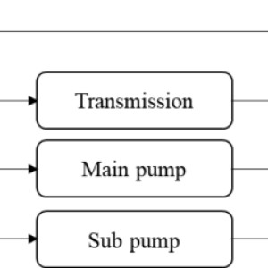
The placement of parts becomes important during the design of electric tractors. Figure 1 shows an illustrative schematic of ICE tractor power flow. Notably, engine power is largely transmitted to the PTO motor, driving axle and hydraulic system, and PTO power is transmitted directly.
Driving axle power is transmitted through the transmission system, and the power of hydraulic devices such as three-point hitches and steers is transmitted through the main pump or sub pumps. Therefore, even when designing electric tractors, the power transmission system can be configured in various ways depending on the number of motors and the connection configuration. In this study, the main power sources of the tractor were selected and analyzed by dividing them into three types: the PTO motor, the driving axle, and the hydraulic system.
Fig.1
Diagram of ICE tractor power flow.
Full size image[1]e-powertrain
The e-powertrain is configured to transmit power via an electric drive system with a battery, motor, and inverter as the power source rather than a diesel engine. Each electric motor is connected to a driving axle, PTO motor, and hydraulic system. Figure 2 shows representative types of electric drive power transmission systems.
In Europe, PTO motors exist for the rear, front, and sides. However, only one was considered for the Korean tractor structure. Although the front and rear axles can be separated, they were designed to comprise only one driving axle.
The number of motors ranges from one to three depending on the driving axle, PTO motor, and hydraulic pump connections. Notably, (a) shows the case in which one motor is used, (b)-(d) show the case in which two motors are employed, and (e)-(j) show the case in which three motors are used. Because limited motor specifications can be selected and analyzed, cases (b), (e), and (f) were chosen and investigated.
In most e-powertrain types, the motor of the hydraulic system for steering and for lifting and lowering the three-point hitch is configured separately. The gear pump is always driven at the rated rotational speed. When connected to the driving axle motor or the PTO motor, a gear pair should be added.
This makes it difficult to save space. Accordingly, the motor of the hydraulic system was considered a separate configuration. The corresponding structures are shown in (b), (e), (f), and (i).
However, the structure shown in (i) was determined inefficient and excluded because it combined a motor in parallel with a hydraulic system with a relatively low motor output.
Fig.2
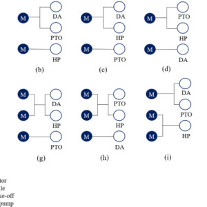
Representative types of power transmission systems for electric tractors.
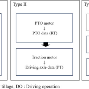
Full size image[2]Various motor types were selected for calculating the required motor specifications and analyzing the characteristics, as shown in Fig. 3. Type I consists of a single motor. In this type, power is transmitted from one motor to the driving axle and PTO motor.
Type II consists of dual motors, and power is transmitted to the driving axle and PTO motor. Type III is identical to type II in that it comprises dual motors, but power summation and splitting are enabled through the adoption of a PGS. In all types, the hydraulic system was designed to be driven by a separate motor.
Fig.3
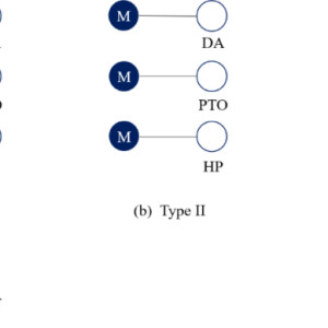
Selected e-powertrain types for electric tractors.
Full size image[3]Figure 4 shows a schematic of type I. This type represents an engine-electric motor replacement method. The power of the electric motor is transmitted to the driving and PTO axles.
The ICE powertrain is applied equally between the input shaft of the electric motor and the output shaft of the driving and PTO axles. This structure was developed by John Deere, Kubota, Solectrac, and Monarch for small tractors that perform agricultural operations involving low loads. It was rapidly developed by applying the ICE powertrain to the existing tractor line-up.
Fig.4
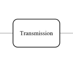
Schematic of a type I motor comprising a single motor.
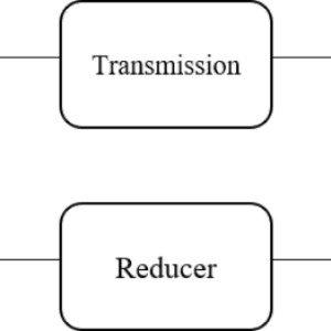
Full size image[4]Figure 5 shows a schematic of type II. In this type, the PTO and traction motors are used separately. Many geartrain arrangements and clutches are needed to control the tractor and PTO speeds with one motor.
In this structure, the required speed range can be efficiently controlled because power is transmitted separately to the driving and PTO axles. Tractors use more than 80% of the engine rated power for the driving and PTO axles during high-load agricultural operations such as plow tillage, towing operation, and rotary tillage. Type II is suitable for medium-sized tractors of 40 kW or more.
Kubota, Daedong, and TYM have developed dual-motor-type electric tractors.
Fig.5
Schematic of a type II system comprising dual motors.
Full size image[5]Figure 6 shows a schematic of type III. This dual-motor type is similar to type II. However, power is coupled and distributed through a PGS according to the working mode.
The power flow of type III is shown in Fig. 7 according to the power summation and split modes. In the power summation mode, the power outputs of the PTO and traction motors are combined and transmitted to the driving axle. This mode is used for high-load operations such as high-speed driving operations, plow tillage, and towing operations.
In the power split mode, the power outputs of the PTO and traction motors are transmitted to the PTO and driving axles, respectively. This mode is used for PTO operations such as rotary tillage. An electric tractor with this structure has recently been developed into a prototype at universities and research institutes in China.
In addition, e-powertrains with dual motors and a PGS are actively studied.
Fig.6
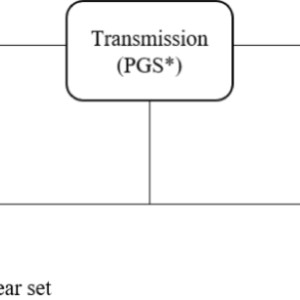
Schematic of a type III system comprising two motors and a PGS.
Full size image[6]Fig.7
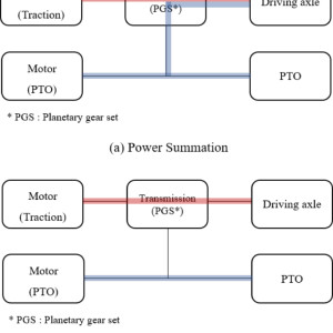
Power flow of type III according to the working mode: (a) Power summation and (b) power split.
Full size image[7]Agricultural workload data
The workload data, such as the engine, driving axle, and PTO workload data, were plotted as a T-N curve to calculate the motor specifications needed for the different e-powertrain types. The workload data used in the analysis were extracted from previous research15.
The data were measured using a 55-kW diesel engine tractor of the same output, and field experiments were conducted on the main agricultural operations such as plow tillage, rotary tillage, and driving operation in Korea. Torquemeters were installed on the axle and PTO, and the torque generated on the axle and PTO was measured through plow and rotary tillage. At this time, the axle torque was calculated as the sum of four wheels.
The measured data were converted into a T-N curve and analyzed according to the type of power transmission system. Figure 8 shows the T-N curve of the measured engine data of a 55-kW agricultural tractor during agricultural operation. During plow tillage, the engine speed ranged from 939 to 2328 rpm, and the maximum torque was 191 Nm.
During rotary tillage, the engine speed ranged from 1922 to 2328 rpm, and the maximum torque was 199 Nm. During driving operation, the engine speed ranged from 640 to 2300 rpm, and the maximum torque was 219 Nm. Accordingly, during agricultural operation, the engine speed ranged from 640 to 2328 rpm, and the engine torque ranged from 3 to 219 Nm.
The detailed engine data, which are used for calculating the required motor specifications, are listed in Table 1.
Fig.8
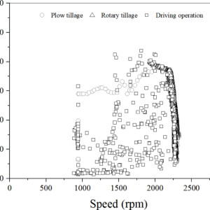
T-N curve of the measured engine data of the 55-kW agricultural tractor during agricultural operation.
Full size image[8]Table 1 Measured engine data of the 55-kW agricultural tractor during agricultural operation.Full size table[9]Figure 9 shows the T-N curve of the measured driving axle data of the 55-kW agricultural tractor during agricultural operation. During plow tillage, the axle torque ranged from 65 to 21,062 Nm, and the maximum speed was 19 rpm. During rotary tillage, the axle torque ranged from 85 to 6892 Nm, and the maximum speed was 17 rpm.
During driving operation, the axle torque ranged from 72 to 8070 Nm, and the maximum speed was 118 rpm. Accordingly, the axle torque during agricultural operation ranged from 65 to 21,062 Nm, and the maximum speed reached 118 rpm. The detailed driving axle data, which are used for calculating the required motor specifications, are listed in Table 2.
Fig.9
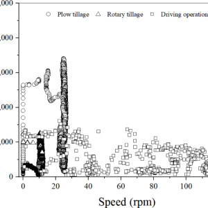
T-N curve of the measured driving axle data of the 55-kW agricultural tractor during agricultural operation.
Full size image[10]Table 2 Measured driving axle data of the 55-kW agricultural tractor during agricultural operation.Full size table[11]Figure 10 shows the T-N curve of the measured PTO data of the 55-kW agricultural tractor during agricultural operation. The PTO speed during rotary operation ranged from 559 to 581 rpm, and the PTO torque ranged from 120 to 636 Nm. The average PTO torque reached 476 Nm at the L3 gear stage and 414 Nm at the L4 gear stage.
Notably, a higher torque occurred at the L3 gear stage than at the L4 gear stage. Because the PTO gear stage was set to stage 1, the PTO speed was similar at both the L3 and L4 gear stages, with an average PTO speed of 570 rpm. The detailed PTO data, which are used for calculating the required motor specifications, are listed in Table 3.
Fig.10
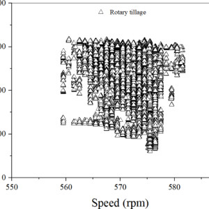
T-N curve of the measured PTO data of the 55-kW agricultural tractor during agricultural operation.
Full size image[12]Table 3 Measured PTO data of the 55-kW agricultural tractor during agricultural operation.Full size table[13]Methodology
Motor T-N curves for each type were generated via load data measured during agricultural operations. When electrifying an existing power transmission system, an increase in the gear ratio can reduce the motor specifications. Conversely, a reduction in the gear ratio results in an increase in the motor specifications.
In this study, motor specifications similar to those for the existing ICE powertrain gear ratio were selected. Figure 11 shows the calculation process for the required motor specifications according to the e-powertrain type. The type I T-N curve was generated by including driving axle and PTO data.
Accordingly, when data summation and the gear ratio were applied, the curve was similar to that of the engine data and was selected accordingly. The type II T-N curve was selected on the basis of the gear ratio applied to the driving axle and PTO data. The T-N curve of the traction motor was generated on the basis of axle data collected during plow tillage.
The T-N curve of the PTO motor was used as a source for PTO data during rotary tillage. For dual-motor types II and III, the gear ratio connected to the PTO motor was set to the existing PTO gear ratio, and the gear ratio connected to the traction motor was set to enable the application of a spiral bevel gear and final reduction gear, except for the main shift and range shift. The torque and speed of the PTO and traction motors were calculated via Eqs. (1)-(4).
The PTO gear ratio is calculated as 4, the gear ratio of the range shift is calculated as 5.7, and the gear ratios of the spiral bevel gear and final reduction gear are calculated as 3.2 and 10.2, respectively. The gear ratio was set based on an engine tractor with the same output. In addition, the efficiency of the PTO axle to the engine and the driving axle to the 4WD axle were calculated considering the number of gear pairs.
At the time, the efficiency of the helical gear was applied as 0.98, and as a result, ({eta }_{PTO}) of 0.94 and ({eta }_{DA}) of 0.92 were applied.
Fig.11
Calculation process for the required motor specifications according to the various e-powertrain types.
Full size image[14]Type III was configured to transmit power to the driving and PTO axles through the brake during PTO operation and to the axle through power combination during driving and towing operations. Therefore, the T-N curve of the PTO motor was selected to match that of type II. The T-N curve of the traction motor was selected to satisfy the axle data during rotary tillage.
The curve was finally verified by examining whether the combined torque of the PTO and traction motors satisfied the driving axle data during plow tillage. ££T_{PM} = frac{1}{{ eta_{PTO} }}frac{1}{{ GR_{PTO} }} T_{PTO} ,££ (1)
££N_{PM} = GR_{PTO} times N_{PTO} ,££ (2) where (T_{PM}) is the torque of the PTO motor (Nm), (N_{PM}) is the speed of the PTO motor (rpm), (eta_{PTO}) is the efficiency of the PTO axle to the engine (%), (GR_{PTO}) is the gear ratio of the PTO axle to the engine, (T_{PTO}) is the torque of the PTO axle (Nm), and (N_{PTO}) is the speed of the PTO axle (rpm).
££T_{TM} = frac{1}{{ eta_{DA} }}frac{1}{{ GR_{DA} }};T_{DA} ,££ (3) ££N_{TM} = GR_{DA} times N_{DA} ,££
(4)
where (T_{TM}) is the torque of the traction motor (Nm), (N_{TM}) is the speed of the traction motor (rpm), (eta_{DA}) is the efficiency of the driving axle to the 4WD axle, (GR_{DA}) is the gear ratio of the driving axle to the 4WD axle, (T_{DA}) is the torque of the driving axle (Nm), and (N_{DA}) is the speed of the driving axle (rpm).
References
- ^ Full size image (www.nature.com)
- ^ Full size image (www.nature.com)
- ^ Full size image (www.nature.com)
- ^ Full size image (www.nature.com)
- ^ Full size image (www.nature.com)
- ^ Full size image (www.nature.com)
- ^ Full size image (www.nature.com)
- ^ Full size image (www.nature.com)
- ^ Full size table (www.nature.com)
- ^ Full size image (www.nature.com)
- ^ Full size table (www.nature.com)
- ^ Full size image (www.nature.com)
- ^ Full size table (www.nature.com)
- ^ Full size image (www.nature.com)