Battery Electric Vehicle Technology Unravelled
Battery Electric Vehicle Technology Unravelled
I was convinced that electric vehicles were impractical and thought most the specimens that we had were meant for city rides until 2022. What we had in market looked like haphazardly executed EV conversions of ICE cars.
I'm a long-distance guy. I hardly have any daily commute requirements that require a car.
EV at the time did not appeal in my use case. Come 2024, more specifically with Mahindra launching their BE 6 and XEV 9E, my thoughts reversed. I have been a Mahindra customer for the last 10 or so years, owning two ICE vehicles during this time.
Though many would differ in opinion on M&M reliability, I have found them to be among the best purchase decisions in my life. So, when they launched their purpose-built EVs, they got my attention for real. 
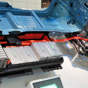
Figure 1.
Battery Electric Vehicle drive train (courtesy of Wikipedia) Two things struck me that made the Mahindra-borne EV thing stick in my mind. One was they came with 280bhp motors, and the other was the 79kWh battery packs, that M&M claimed, could charge from 20 to 80% in 20 minutes.
So, when the vehicles finally came to the distributors, like every vehicle enthusiast, I went and took a test drives back to back. BE 6 was the first, and oh boy, was I impressed! But when I drove XEV 9E, I was flattered.
The small complaint that I had with BE 6 about its suspension being a little hard was gone in the 9E, and the car felt just perfect. The car had all the bells and whistles, had tremendous power, looked good, had a range of about 500 km, and an acceptably quick charging speed. My own '22 model petrol automatic 'lifestyle' car felt less appealing after that test drive.
Because there were no purchase plans, even during the Mahindra vehicle test drives, I simply did not bother about the technology behind all that. I read the brochures, took test drives and listened to the sales executive's hyperbolic feature explanations. I must confess that I was mostly ignorant about the technological advancements behind the EVs, nor was I interested in them.
After the pleasant experience of EV test drives, I was convinced that time of the EVs had come to our shores as well.
So, when it was time for replacement of my family car back in my hometown, I suggested that my dad consider an EV also as an option. At home, my dad had set up a solar power unit last year and was producing a lot of excess energy. EV was looking to be a very good option in his use case.
So, I decided to dig deep for information on EV technologies. Oh boy, did I find a lot and learned a lot! I'm sharing some of that over here for all those who are interested or considering buying an EV.
Since this is going to be a long read, the topics that I'm going to try to explain are given below in a list so that one can find the one they are looking for easily.
1. EV Motor Technology. Why they need permanent magnets?
2.
Battery technology and why some manufacturers ask you to charge all the way to 100% and some don't!
3. Why is an old school 12V battery needed in addition to the high voltage battery pack?
4. Electric Vehicle Supply Equipment (EVSE), and why are the home wall chargers this darn expensive?
5.
Is it necessary to control regenerative braking as one would with proper gear selection in ICE cars? Is paddle shifter-type regenerative braking control just a gimmick?
6. Brake by wire and why latest EVs have awesome brakes
EV Motor Technology. Why they need permanent magnets
The electric motor in a modern EV is a marvel of electrical and mechanical engineering. Of all the electrical motor types out there, EVs usually get a Permanent Magnet Synchronous AC Motor (PMSM).
For electric motors to do their thing, they need electric power from the battery in an EV. Since batteries supply DC current, why do EVs have AC motors? Why unnecessarily add a DC to AC converter and then use this energy to drive the vehicle?
The answer to this lies in the fact that DC motors are not as efficient or as reliable as AC motors for a multitude of reasons. To start with, normal old-school DC motors need a device called a commutator, which consists of slip rings and carbon brushes. The commutator is the device that generates the required switching of the magnetic field in the rotor for the generation of torque.
Actually, a DC motor converts the DC power supply into AC using the commutator before supplying it to the rotor windings. A commutator is a wear item and needs maintenance. DC motors are also not as size-efficient as AC motors in most applications.
Moreover, the voltage available at the terminals of the HV battery has to be varied at the motor terminals to meet the variable torque demand. Thus, invariably, some kind of power controller has to be there as well. On the other hand, the most common AC motor in use in the industry is the three-phase AC squirrel cage induction motor (SCM).
This one also has good efficiency at its design speed. Construction-wise, AC induction motors are simple, easy to make and maintain. Then why not this one in EVs?
Actually, they were and probably still are used in some EVs. Tesla Model S used this type of motor in its rear wheel drive unit in models with twin motor configuration. SCM can even do regenerative braking by allowing the rotating magnetic field to rotate at a speed slower than the rotor.
However, they are not as efficient near low speed regions and lower efficiency in energy recovery or brake regeneration as Synchronous AC motors, and they also have poorer torque characteristics in comparison to a PMSM motor of equivalent power, especially at high speeds. SCMs are also not as dimensionally compact as similar spec PMSMs. Dual motor EVs with PMSM and SCM combination allow the designers to take advantage of the plus points of both technologies.
One of the advantages of SCM over PMSM is that they incur very little losses during freewheeling of the motor when the vehicle is made to coast on the highway. In case of PMSMs, the magnets in the rotors tend to produce eddy currents in the stator housing, leading to some energy wastage during freewheeling. In case of SCM, since the rotor is essentially a cage made of aluminium or copper, no such losses are incurred during freewheeling or coasting.
So, in a dual motor setup, during cruising at high speeds under low loads, PMSM can be tasked to power the car, and the SCM can be completely switched off for better efficiency. Synchronous AC motors are, in principle, AC generators. The kind that we find in power stations that produce electricity.
These motors use three-phase AC as input power and work at a speed directly proportional to the AC supply frequency. They are very efficient in shaft power production and shaft power recovery during regenerative braking. But the industrial AC Synchronous motors usually come with a Wound Rotor for the generation of a magnetic field in the rotor called WRSM.
This means that these motors also need slip rings and carbon brushes to operate. But these carbon brushes and slip rings are fundamentally different from those found in DC motors. First of all, slip rings in AC synchronous machines do not function as a commutator.
A commutator in the DC motor has to supply full power to the rotor, and it has to switch the power supply to the pole windings multiple times in one revolution of the rotor. This commutation or switching that happens in the DC motor causes arcing and needs constant maintenance and monitoring. In the case of the wound rotor AC Synchronous motor, the slip rings are only tasked with carrying enough current to maintain the magnetic field.
Actual power supply to the motor goes to the stator windings. Also, the slip rings in the WRSM do not have to act as a commutator, so no sparking. Thus, the operating conditions of the slip rings in SM and DCM are far different.
EV equipment manufacturers have gone one step further and have removed the wound rotor from the SM and introduced a Permanent Magnet rotor SM. This was made possible by the invention of very strong rare-earth material magnets like neodymium-iron-boron. PMSMs, as they are commonly known, have no slip rings, have efficiencies of about 97.5% and are very reliable.
One can compare the SM working principle to that of a surfer riding an imaginary, ending wave. The never-ending wave in the motor is the rotating magnetic field produced by the stator windings. The speed of rotation of the magnetic field is governed by the power supply frequency to the motor from the motor controller.
Now, when the surfer has enough momentum and wants to slow down, the surfer generates (rather than riding it) the wave and, in the process, slows down, transferring his kinetic energy to the wave. The energy of the generated wave can be recovered and stored back into the battery for use at a later time. It must be noted that the AC Synchronous motor rotor rotates at the same speed as the Rotating Magnetic Field (RMF) produced by the stator winding.
Since the car moves at speeds from a standstill to the top speed of the EV, the motor controller adjusts the input frequency to the motor based on the rotor RPM. I have discussed a lot about the age-old DC motor technology. But the new kind in the block, the Brushless DC (BLDC) motor, is also gaining popularity in many applications.
They can be found in small fans in computer cooling devices to large industrial ceiling fans, mixer grinders, computer hard drives, DVD drives, washing machines, drone propeller motors, etc. These motors use a DC power supply and utilise an external electronic commutator (no slip rings) for their operation. Synchronous and BLDC motors most often use some form of sensor-based loop feedback from the rotor to determine its location, direction and speed of rotation.
Though BLDC motors need a DC supply, the motor controller converts the same into a crude trapezoidal AC to feed the motor windings. Actually, there are many things in common between the Synchronous and BLDC motors. The reason why WRSM or PMSM are popular in EVs is due to the higher efficiencies of these motors and motor packages.
It should also be noted that companies like Tesla, in their vehicles, use hybrid PMSMs called Interior Permanent Magnet Synchronous Reluctance Motors (IPM SynRM) that are designed to run at very high speeds without loss of efficiency due to losses in the rotor and the stator windings. On the other hand, Nissan Leaf EV has old school (but beautifully designed) wound rotor WRSM - the type with brushes and slip rings. They simply have all the benefits of the SMs but don't use Permanent Magnets.
Effectively evading the Permanent Magnet-related supply chain issues. So, the choice of the type of electric motor in EVs today is largely based on the overall system efficiency, reliability, physical size and cost of production. The choice is affected even by global factors like the availability of raw materials.
At least for the time being, it looks like PMSMs and variations of this general type are going to play an important role in EV propulsion. That said, like ICE engines, EV motors also need cooling. Most of the manufacturers use a water-based coolant to transfer heat from the motor housings to the EV's water-to-air radiator, just like in ICE cars.
Some of the models use an oil spray system inside the motor cavity to effectively remove heat. The oil transfers heat to the radiator fluid via a heat exchanger. To make EV PMSM as cost-effective as possible, manufacturers choose a small form factor for the motor.
This means that to produce reasonable power, these motors have to rotate at much higher RPMs than conventional ICE engines. EV motor RPMs range between 10K and 25 25K. Tata in the Nexon 45 EV uses a motor that has 30-something per cent less permanent magnets in comparison to the older versions.
They claim that the new motor operates at 16K RPM (max) in comparison to the 12k RPM they used in the earlier variants, while being more efficient and lower in noise. To mate these extremely fast shaft speeds to the wheels of the vehicle, EVs use a speed reduction gearbox. This gearbox also needs oil lubrication and cooling.
Typical Torque versus speed characteristics of an EV and ICE at full 'throttle' are shown in the figure below. 
Figure 2. Schematic of EV motor and ICE Torque versus speed characteristics comparison
The EV motor torque plot in the above figure has two broad regions as depicted. Notice that the speed range starts from zero and goes all the way to the full speed of the car using a single speed transmission. In the constant torque region, the car would accelerate at constant tractive force.
As can be seen right from zero speed, full torque is available for this acceleration. In the constant power region, torque and speed are traded for each other in such a way that power remains constant (more or less). In case of ICE cars, the much shorter speed range, poor torque curve and no torque at zero speed can only be tackled using a multi speed transmission and coupler or speed matching device (like a clutch or torque convertor) combo between the engine and the final drive.
This beautiful torque versus speed curve in EV is a direct result of the electronic wizardry inside the motor controller in modern EVs.
The sheer pace at which these things are advancing is simply marvellous. 2. EV battery technology and why some manufacturers ask you to charge all the way to 100% and some don't!
EV battery technologies that we need to discuss here are of two types. Lithium Iron Phosphate (LFP) and Lithium Nickel Manganese Cobalt (Li-NMC, commonly known as NMC) are the most popular EV battery technologies available right now. It is important to note that they both are fundamentally Li ion batteries, in contrast to the new promising entrants like Sodium Ion or solid state ones.
However, use of the latter ones in mainstream EVs is some time from now, though they have the potential to disrupt the battery landscape quite a bit. Moreover, nickel-metal-hydride batteries, though used in Hybrid electric vehicles, have poor efficiencies. There are basically a few qualities all EV batteries must possess to become a viable option for EV charge storage for propulsion.
They are, a. High charge density (kWh per ton)
b.
High safety
c. Low cost of production
d. High efficiency
e.
High longevity I reckon most of the above items are self-explanatory. However, I find it important to discuss the aspect of battery safety and longevity here in some detail.
During development, manufacturers subject these batteries to a plethora of tests to ascertain safety margins to various types of anticipated failures. Like overcharging, short circuiting and mechanical tests. There are even tests that simulate a nail getting through the battery pack to simulate severe mechanical damage that can occur during an accident.
In the safety department, LFP batteries score high over NMC type. LFP blade cell battery from BYD passed even the nail penetration test. If you were to put a nail through your phone battery, most probably you would get your house on fire!
So, passing the blade penetration test by a Li-ion battery is a huge stride in the safety department. The retention of battery capacity over time is expressed as a percentage of charge in comparison to a brand new battery and is called State of Health (SOH). SOH would decline as the number of charge and discharge cycles accumulate in all battery types.
LFP batteries score high in the ability to retain charge over multiple charge-discharge cycles. This is most probably the reason why cars with LFP batteries nowadays come with 15 15-year battery warranty. Where LFP loses out to NMC is with the charge density and outright discharge performance.
Meanwhile, LFP batteries also score in production cost with reduced dependence on minerals like Manganese and Cobalt. No wonder we see a lot of our EVs coming with LFP batteries. That doesn't mean that NMC ones are bad or inferior.
Hyundai sticks with NMC technology in its EVs. And their Creta EV comes with an 8-year warranty on the battery. The device that does the charging and discharging control of the battery in the EV is known as the Battery Control Module or BMS.
To effectively control the battery, the battery BMS has to keep track of the SOC and SOH of the battery precisely. Voltage versus charge of a typical LFP and NMC battery is schematically shown in the figure below. 
Figure 3.
Schematic of Cell Voltage versus SOC of NMC and LFP batteries It can be noticed that LFP and NMC batteries have a relatively flat middle portion where the terminal voltage of the battery cannot be used for accurately estimating the SOC of the battery. In contrast to this, Lead Acid Batteries have a rather steep curve that allows the gradient to be taken for SOC estimation purposes.
Moreover, the low gradient in the voltage gradient middle is particularly pronounced in the case of LFP batteries. So, a combination of strategies for accurate measurement of SOC in which the BCM continuously keeps track of the amount of current drawn from and recharged back. This data is numerically integrated by BCM with time for SOC estimation.
A battery is like a tank full of water. If a flow measurement device is present in the output/input pipe at the bottom of the tank, data from the device can be used to calculate how much water is left in the tank at any given time. However, there shall be a reference level or a reset point in the tank from which all flow integration can start.
This reference can be either a fully empty or a brim situation. This integrated SOC evaluation procedure, called coulomb integration in case of EV battery, along with the voltage as additional information, is used for accurate estimation of the SOC of the EV battery. In case of LFP, due to the flatter (in comparison to NMC) curve in the SOC to voltage plot, the voltage data doesn't give much information to the BCM for estimation of SOC except near the ends.
LFP BCM relies heavily on the Coulomb Integration for the estimation of SOC. But there is a catch. Any, even small, error in measurement of charge flow (current) through the integrator unit or any small numerical inaccuracy in the integration procedure would lead to errors in charge estimation in a cumulative manner.
This is known as integration drift. Any device that works on time-integrated data is bound to have drift errors. Even inertial navigation systems in spaceships and aeroplanes that use gyroscopes have drift issues.
Apollo Spaceships used stars for manual drift correction every now and then. Verner Von Braun's V2 rockets never landed on intended targets in Britain during World War II due to integration drift in its primitive Inertial Navigation System.
In case of LFP batteries, integration drift can be effectively corrected by charging the battery all the way to 100% SOC. At which point there is a significant rise in voltage of the battery that the BCM can detect accurately, here BCM knows for sure that it has reached a 100% SOC.
This is used to reset the coulomb integrator data for the correct estimation of SOC from that point on. So, LFP batteries are by design required to be charged to 100% SOC every once in a while for reference point correction. If this is not done, drift errors can accumulate and give erratic SOC readings that are so common in TATA EVs' LFP batteries, with people complaining of sudden range drops, especially towards the lower 30% of the SOC region.
I infer that these complaints are due to BCM correcting or augmenting the SOC figure using the voltage measurement data, which becomes possible due to a larger voltage gradient near the lower SOC region.
On the other hand, NMC battery totally hates getting charged all the way till max SOC. They are happy with small charge and discharge cycles. NMC technology is also considered to be more suitable for relatively cold climatic conditions in comparison to LFP, being better for hot conditions.
NMCs are also more suitable for faster discharge rates, together with superior charger density, making them more suitable for performance vehicles. There is some data that suggests possible battery degradation with maintaining high SOC continuously in both battery types. Most manufacturers advise against storing (for a long time) the car at high SOC for a long time.
Battery degradation in general is proportional to its voltage (SOC) as well as operating temperature (which in turn depends on environmental and operating conditions). So, charging the car every time to 100% or cycling it to a full charge, or worse, cycling near 100% may not be best practice in any battery type.
For LFP batteries, at least the best strategy seems to be charging all the way to 100% on AC slow charging and then allowing the battery to discharge to about 20% and then going back to 100%. But that's what one should do from a longevity point of view.
Tesla, in their Model 3 LFP battery variant, advises customers to keep the car connected to the AC wall charger when the car is not in use. So, it is advisable to follow the instructions given in the owner's manual of the EV to protect the warranty. Manufacturers know better.
3. Why is a 12-volt battery needed when a much larger one is already present in the vehicle? This is indeed a peculiar situation.
After all, an EV has a huge battery to tap from for all the devices that run on the traditional 12V lead acid battery found in an ICE car. If HV is argued to be unnecessarily dangerous inside the car, a DC to DC converter can reduce the voltage from the HV battery for powering all the accessories. However, a separate 12V battery is needed for safety purposes in an EV, in addition to the legacy advantages of retaining a proven vehicular technology.
All the EV manufacturers seem to be following the 'If it ain't broke, don't fix it strategy (I did not make this one up, I found this line in the Mazda USA webpage on this topic)! On the safety aspect, EV motor controllers are designed in such a way that a 12V battery is needed for switching ON and running the EV. In addition to this, the 12V battery runs all the electrical gadgets in the car.
The 12V battery also gets charged by the HV battery via a DC to DC converter. Further, during a collision or a fire emergency, the HV battery needs to be electrically isolated from the rest of the systems by severing the connection at the HV battery contactor. After this is done, something still needs to power the essential systems like brake lights, hazard lights, horns, etc., to draw the attention of fellow road users to the accident car.
This can only be achieved using power from a separate battery. Why a lead acid battery? Mostly cost effectiveness.
A 12 Li-Ion battery would be equally good. 4. Electric Vehicle Supply Equipment (EVSE), and why are the home wall chargers this darn expensive?
The home wall charger that comes with BE 6 and XEV 9E is available in two options, a 7.2kW one and an 11kW one, costing about 50k and 75k respectively. I found myself wondering what these things have in them to make them this expensive. Before we get into that, I find it important to explain the general electrical layout of modern EVs via a schematic.

Figure 4. Schematic of EV charging So, there is a charger on board the EV.
This is the device that does the charging while the vehicle is connected to the wall charger at home. At home, the power available is AC. The wall-mounted EVSE connects the on board charger in the car to the home electrical power supply safely.
That's it. So, where is all the money going on the AC Wall Mounted EVSE? To answer that, at least partially, I will explain the expected functions of home EVSEs
a.
Since the onboard AC charger on an EV is rated at something like 11kW (just an example, in case of Nexon EV it is 6.6kW), and your house connection only allows 7.2kW, the EVSE should be capable of telling the car charger to draw power not more than 7.2kW. Thus, even if you buy an EVSE from the car manufacturer rated at 11kW, if your home connection does not allow for more than 7.2kW, you will be stuck with the lower power charging. During installation of the EVSE, the technician would go through the relevant documents from your electricity service provider and set up the EVSE according to how much power it can draw.
b.
The EVSE should start the power supply only after all the connections are made completely. Likewise, the EVSE should be capable of cutting off power before the connections are severed. This is important from two fronts.
First, from a safety point of view, there shall be no power at the leads until the connector is firmly connected to the female socket in the car. If not for this feature, somebody might get electrocuted if they were to accidentally drop the connector in a puddle of water with them standing in it. Secondly, if power were present during connection and disconnection processes, sparking would occur at the leads and would lead to the premature demise of the connector in the EVSE cable and/or car side.
c.
The EVSE should be capable of detecting proper earthing.
d. Most of the EVSEs also provide data on real-time power draw, scheduling of charging, securing of the charger using RFID tags, etc., and communication with the user via WiFi-based mobile phone apps.
Of all the safety functions of the EVSE, the decision on whether power is to be sent through the cable or not is the most important. This is achieved using a device known as a contactor inside the EVSE.Contactors are costly. A 30A contactor (for 7.2kW EVSE) would cost as much as 10K. The contactor has two parts to it.
One part does the actual switching, and the other part provides the mechanical force actuation for the switching. The actuation is provided by a low-voltage coil (electromagnet), powered by the EVSE electronic control module.
There are a few pretty clever bits in the EVSE, the supply cable and in the EV itself that make the overall process of charging safe and efficient. The EVSE cable connector in India has a special pin configuration.
This connector is manufactured to meet the CCS Type 2 IEC standard. CCS stands for Combined Charging System, which implies that the same connector can be used for AC home charging and DC fast charging, though the connector pins utilised for the two different charging modes are different. In the AC side of the CCS2 connector, there are seven pins shown in the schematic.
Of these, the Proximity Pilot and Control Pilot pins help the EVSE meet the safety functions in a clever and simple way. The pilot pin is grounded to the Earth pin via a standard resistor. Meanwhile, on the EV side, the pilot port of the female receptacle is grounded to the earth port via a resistor.
By measuring the voltage across the resistor in the EVSE, the control module in it knows whether a car is connected to it or not. That is when the connector is not connected, the voltage across the pilot pin with respect to the earth would be let's say A Volts, after connecting to the EV, the voltage would change to B volts because of the additional resistor at the EV side, which the EVSE can sense. After the connection is made, the EVSE would send a 1 kHz Pulse Width Modulated signal via the Control Pilot in the connector.
Using the Pulse Width, the EVSE tells the EV how much power it is allowed to pull. Once this is also done, the EVSE closes the contactor in it and sends power to the EV charger. During this time, the EV would also mechanically lock the connector in its receptacle so that it is not inadvertently pulled out during the charging process.

Figure 5. CCS Type 2 Charging port DC fast charging is not very different in the process; however, the pins that the EV would utilise would be different from the AC charge pins.
During the process of DC fast Charging, the on board charger in the car sits idle. The function of the on board charger is taken over by the DC EVSE. The DC EVSE is expected to supply the right voltage and current based on the type of battery in the EV and its charging curve.
So, the EV would communicate with the EVSE and tell it how much voltage and current it wants to draw. The process of communication between the EV and EVSE via the Control Pilot is different and a lot more complicated than AC charging at home. But the question of why AC home wall-mounted EVSEs are this darn expensive is still not answered.
Probably the thick copper cables, the expensive connector, etc., would add significant cost. All said, it still looks like the devices are unnecessarily expensive. If someone knows better, please do let me know.
The elephant in the room is whether the advertised DC fast charging speeds by manufacturers are actually achievable in real-world situations or not. Most of the DC fast chargers in the country are rated at about 60kWs or below. When two cars are connected to the same charger, the charging power usually falls to half of the capacity.
Moreover, batteries don't charge at the same speed from zero to full. All these factors affect the practically achieved total time at a charging station in the present scenario. Making EVs a lot less attractive for people who often do long drives.
5. Is it really necessary to control regenerative braking as one would with proper gear selection in ICE cars? Is paddle shifter-type regenerative braking control just a gimmick?
Regenerative braking has the potential to recover up to about 30% of the energy. However, practical recovery percentage in a vehicle would depend on factors like driving conditions, including speed, acceleration, deceleration, the selected drive mode, selected regeneration mode, etc. Selecting a high regeneration setting is not always the most efficient solution.
Brake regeneration tries to recuperate the kinetic energy of the moving car back into the battery. For this to happen effectively, friction brakes are to be used as little as possible for decelerating the car. Moreover, brake regeneration is not one hundred per cent efficient.
Since the driver has no direct control over how much of the brake force is produced from brake regeneration, what he has to do is use low decelerations as much as possible, as explained in the I-VBAC section. When the car is being driven at highway speeds, since brake regeneration is not one hundred per cent efficient, you don't want the car to unnecessarily slow down due to brake regeneration when you lift off the accelerator pedal with the intention just to coast at constant speed. The energy recovered from regeneration will always be less than the energy stored in the car as kinetic energy during coasting.
So, during highway speeds with open roads, the regeneration setting shall be as low as possible. If there is a zero setting, select it. Our roads are not always open for us to coast effectively, and we would find ourselves slowing down behind trucks and other slow-moving vehicles too often.
So, the brake regeneration shall be selected prudently based on driving conditions on the highway. Meanwhile, in our cities where we have to accelerate and brake very frequently, a regeneration setting somewhere in the middle of the pack shall be used so that friction brakes are used as low as possible in slowing down, at the same time, we don't lose out on energy conversion efficiency. In bumper-to-bumper traffic, the maximum regeneration setting shall be used.
If there is one pedal driving as an option, select it. The reason for getting lower drive range out of the battery on the highways in comparison to driving in urban settings is not because of a lack of brake regeneration on the highways due to less traffic. The lower efficiency is simply because of higher energy losses due to much higher air and rolling resistances incurred at highway speeds in comparison to city speeds.
Air drag increases proportional to the vehicle velocity squared. A lot of the energy is used to simply push the car through the air. Try to drive at 60kmph down the highway with brake regeneration set to zero, you would most often get the highest battery range.
Drive at 120kmph, range would drop like a brick. Drive at 120kmph with regeneration setting at max on open roads, the range would drop even further. I believe that this paddle shifters type brake regeneration control is useful in effectively controlling the regeneration mode on the fly.
I do not know whether cars with paddle shifter-type regeneration control allow downshifting during braking. I mean, somewhat like engine braking used in ICE cars. If that is the case, effective regeneration control and improved range can be realised by someone who knows what he is doing.
Continued in next post.
Last edited by arunpools : 9th August 2025 at 14:14.